
TECHNICAL NOTEBOOK / FIELD MEASUREMENTS
The network is one stage of the setup.
Before sending a measurement from the field, check the power supply, UART, SIM, network registration and server-side reception separately.
1. Identify the board before connecting it
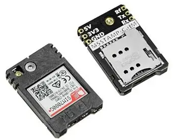
The Quiet Bee path uses a M5Stamp CAT-M based on the SIM7080G. A bare SIM7080G is a component for integration, with its own supply requirements and logic levels. It is not wired directly like a development board. Do not assume that the modem's native UART is 3.3 V compatible.
For the M5Stamp, use the S003 documentation and schematic to identify its power input and level-adapted UART signals. The source setup specifies 5 V and GND for this board, with a supply capable of handling radio transients. Do not supply the modem through a GPIO.
2. Cross the UART signals
| Classic ESP32 | Modem board | Check |
|---|---|---|
| GPIO16: RX | Level-adapted external TX | The modem transmits to the ESP32. |
| GPIO17: TX | Level-adapted external RX | The ESP32 transmits to the modem. |
| GND | GND | Common ground is required. |
| Dedicated power supply | Input suitable for the board | Check voltage and current in its documentation. |
The field code reserves GPIO25 for a relay and GPIO26 for a buzzer, but does not drive them. They are not universal POWERKEY pins. On the M5Stamp in this path, internal POWERKEY/STATUS controls are not added to the external wiring. Also check GPIO16/17 availability on your ESP32 variant, particularly with PSRAM.
3. Test UART alone from Arduino IDE
This educational serial bridge lets you enter AT commands in the monitor at 115200 baud with CR or CR+LF line endings. It does not power the modem, control its start-up or send sensor data. The modem baud rate must match your configuration.
#include <Arduino.h>
HardwareSerial modem(2);
void setup() {
  Serial.begin(115200);
  modem.begin(115200, SERIAL_8N1, 16, 17);
}
void loop() {
  while (Serial.available()) modem.write(Serial.read());
  while (modem.available()) Serial.write(modem.read());
}
If AT receives no response, do not start changing the APN. First check the power supply, modem boot state, baud rate, levels and RX/TX crossing. Unsolicited modem messages may arrive between responses: production firmware must handle them without confusing them with the end of a command.
4. Read status using AT commands
| Command | Purpose | Interpretation |
|---|---|---|
| AT | Test communication | OK confirms only UART communication. |
| ATI | Identify modem and firmware | Keep this response with your test results. |
| AT+CPIN? | Read SIM status | READY means the SIM is usable, not that the network has been joined. |
| AT+CSQ | Read a radio indicator | 99 may indicate an unknown value; it is not a usable level. |
| AT+CEREG? | Read LTE registration | Status 1 or 5 normally indicates home or roaming registration; examine the complete response. |
| AT+COPS? | Identify the operator | Compare with the networks available for your SIM and country. |
| AT+CGATT? | Check packet attachment | Attachment does not prove that a usable data session exists. |
| AT+CGDCONT? | Inspect PDP contexts | Check the context and APN before making changes. |
To define an IPv4 context, a common form is AT+CGDCONT=1,"IP","APN_FROM_PORTAL". LTE-M selection, context activation and transport commands depend on the SIM7080 firmware and the context used by the application stack. Do not combine SIM800, SIM7000 and SIM7080 sequences at random. Consult the AT manual for the version identified by ATI and wait for each command's response.
5. Choose and activate a 1NCE SIM
- On the official 1NCE site, check offer eligibility, countries, available LTE-M networks, SIM format and data allowance/duration terms.
- Order the format compatible with your board's holder. Do not infer the format from the modem name.
- After receiving it, identify the ICCID in the portal and check activation and data availability.
- Read the APN listed for this SIM in the portal. SIMs from different platforms or generations may use sensor.net or iot.1nce.net; do not copy an APN without checking it.
- Configure the IPv4 context according to the portal and modem documentation, then check registration and the session.
Prices, terms and coverage can change: this article promises neither a fixed price nor connectivity at a particular plot. A coverage map does not replace a test at the actual antenna height, with the intended enclosure and power supply.
6. Prove reception, not just transmission
A test packet should contain a technical identifier, a sequence number, a value and its unit, and a timestamp or its status. Compare the ESP32 log with the point received on the server. Then test a duplicate packet and a network outage; an acknowledgement must identify the packet concerned.
The field project sources provide a UDP collector with HMAC-SHA256 signing. A signature protects authenticity and integrity; it does not encrypt the content. This publication does not deploy that collector, open a port or make quiet-bee.fr a UDP destination. Prepare your own destination and network policy; for sensitive information, choose a properly verified encrypted transport.
7. Prepare a field test notebook
Record the board reference, firmware, antenna, power supply, operator, time, connection duration and server result. Hide ICCID, IMSI and secrets before publishing. Compare a successful test with a failure without treating missing reception as a zero measurement. Check additional sensor pins against their schematics; the SHT85 must be read and checked independently of the modem.
Sources and references
- M5Stack: Stamp CAT-M and schematic ↗
- SIMCom: SIM7080G and documentation ↗
- 1NCE: APN changes ↗
- 1NCE: APN settings ↗
- 1NCE: check offers and coverage ↗
The schematics for your hardware reference and the documentation for your software version take precedence over a generic example.