
LESSON 03 / Years 12 → 13 · ADC and PWM
Measure a voltage.
Move from the continuous world to a digital value.
The challenge
Vary brightness with a potentiometer. Distinguish the input voltage, the number returned by the converter and PWM control.
Equipment: UNO R4, 10 kΩ linear potentiometer, red LED and 1 kΩ resistor. Identify the wiper in the component data sheet: the drawing shows its functions, not a universal pin order.
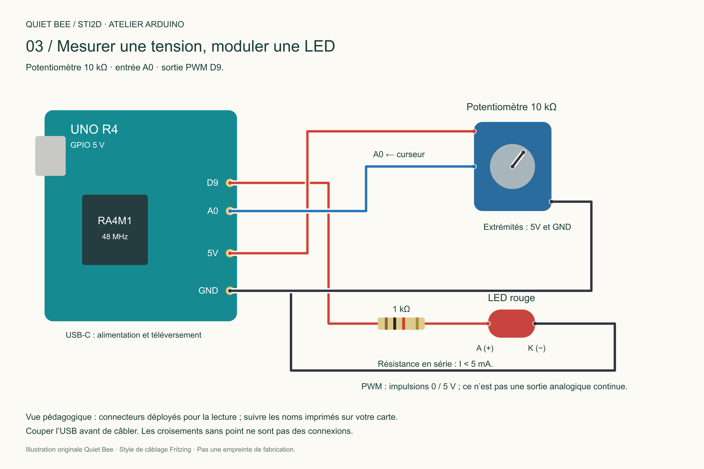
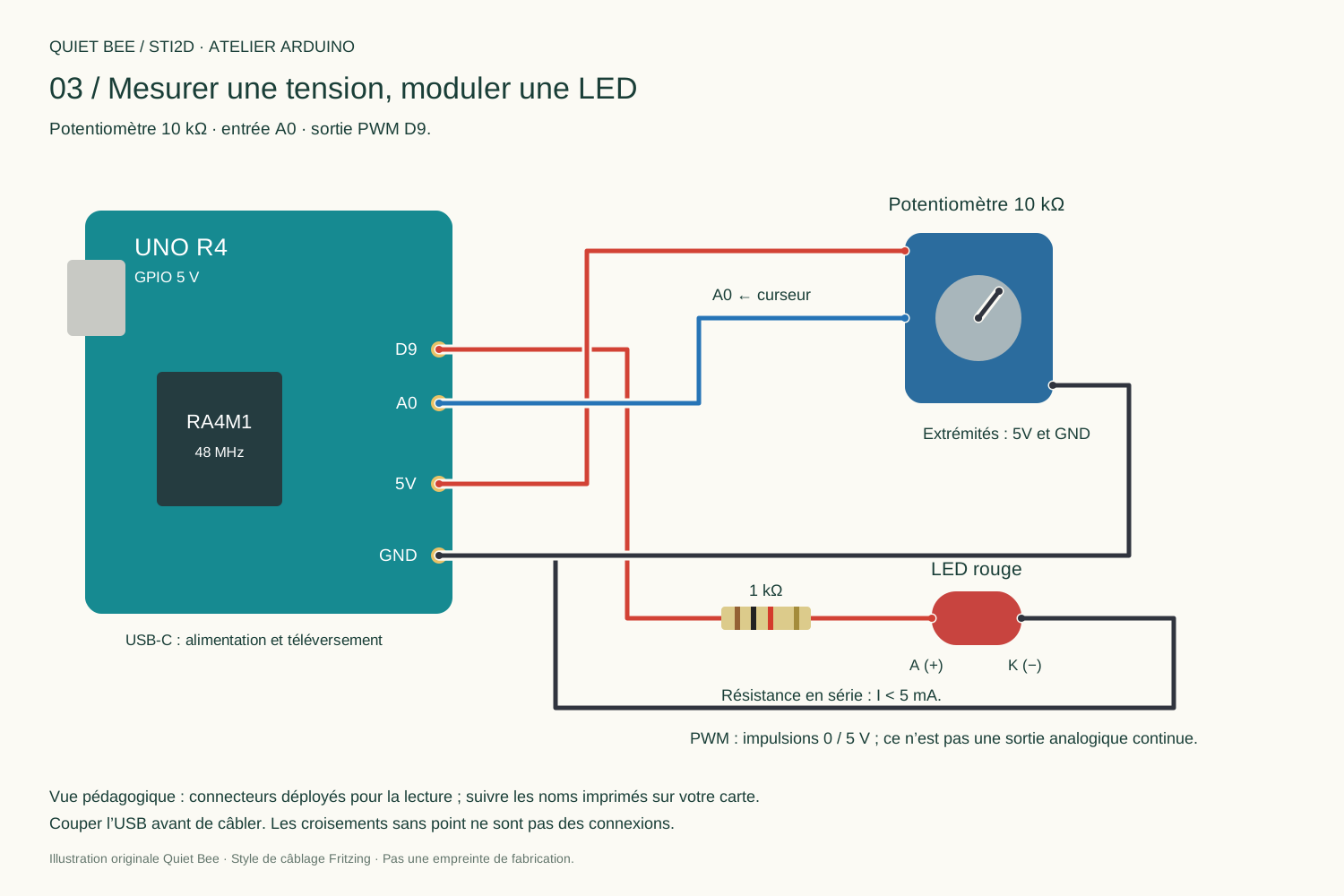
Wire the circuit
| Component | Connection |
|---|---|
| Potentiometer ends | 5V and GND |
| Wiper | A0 |
| D9 | 1 kΩ then LED anode; cathode to GND |
The potentiometer forms a voltage divider; A0 samples the wiper voltage. Check that no position creates a 5V/GND short circuit.
The complete program
03_analogique.ino
Complete project ↓// Potentiometre lineaire 10 kohms : extremites 5V/GND, curseur A0.
// LED : D9 -> resistance 1 kohm -> anode ; cathode -> GND.
constexpr uint8_t POT = A0;
constexpr uint8_t LED = 9; // Broche PWM sur UNO R4.
unsigned long dernierAffichage = 0;
void setup() {
Serial.begin(115200);
pinMode(LED, OUTPUT);
analogReadResolution(10); // Valeurs de 0 a 1023, choix explicite.
analogWriteResolution(8); // Rapport cyclique code de 0 a 255.
}
void loop() {
const int brut = analogRead(POT);
const uint8_t commande = (uint32_t(brut) * 255U) / 1023U;
analogWrite(LED, commande);
if (millis() - dernierAffichage >= 200) {
dernierAffichage = millis();
Serial.print("ADC="); Serial.print(brut);
Serial.print(" ; PWM="); Serial.print(commande);
Serial.print(" ; U estimee=");
Serial.print(brut * (5.0f / 1023.0f), 3);
Serial.println(" V (reference supposee 5.0 V)");
}
}
From volts to a number
The code sets 10 bits: 2¹⁰ = 1024 codes, from 0 to 1023. The estimate U ≈ raw × 5 / 1023 assumes a 5.0 V reference. The actual supply and converter characteristics introduce differences.
The UNO R4 also supports 14 bits: more codes alone do not guarantee greater accuracy. Assuming 5.0 V, the theoretical step is 5 / 1024 ≈ 4.88 mV at 10 bits.
uint32_t(brut) widens the calculation before multiplication. The result is mapped to 0…255 for 8-bit PWM. At the midpoint, duty cycle is close to 50%: D9 alternates between 0 and 5 V; it is not a constant 2.5 V voltage. A0's DAC function is not used here.
YOUR TURN / YEAR 12
Record ADC and PWM at the ends and midpoint. Distinguish resolution and voltage.
GOING FURTHER / YEAR 13
Switch to 14 bits: which constants must change? Compare the estimated voltage with a multimeter reading.
Suggested answers
Configure analogReadResolution(14), replace both 1023 denominators with 16383 and keep 255 for PWM. There are 16384 codes; the theoretical step is about 0.305 mV at 5 V, without guaranteeing that accuracy.
Next step: Acquire a temperature →
SOURCES AND FURTHER READING
Check the documentation.
- Arduino UNO R4 Minima · UNO R4 WiFi
- Arduino: analogue converter resolution
- Arduino: WiFiS3 examples
- Analog Devices : DS18B20
- OneWire · DallasTemperature
- Éduscol: STI2D curricula and resources
Original Quiet Bee content. A suggested progression for working on the information chain, prototyping and validation; it does not replace the curriculum or your teacher's instructions.