
LESSON 01 / Year 12 · Digital output
Control an LED.
An output, a current, a timing diagram.
The challenge
Blink an external LED without blocking the loop. Before running the code, draw the state of D8 against time.
Equipment: UNO R4, red LED, 1 kΩ resistor, wires and breadboard. To test without wiring, you can use the built-in LED with LED_BUILTIN, then move to this lesson's external LED.
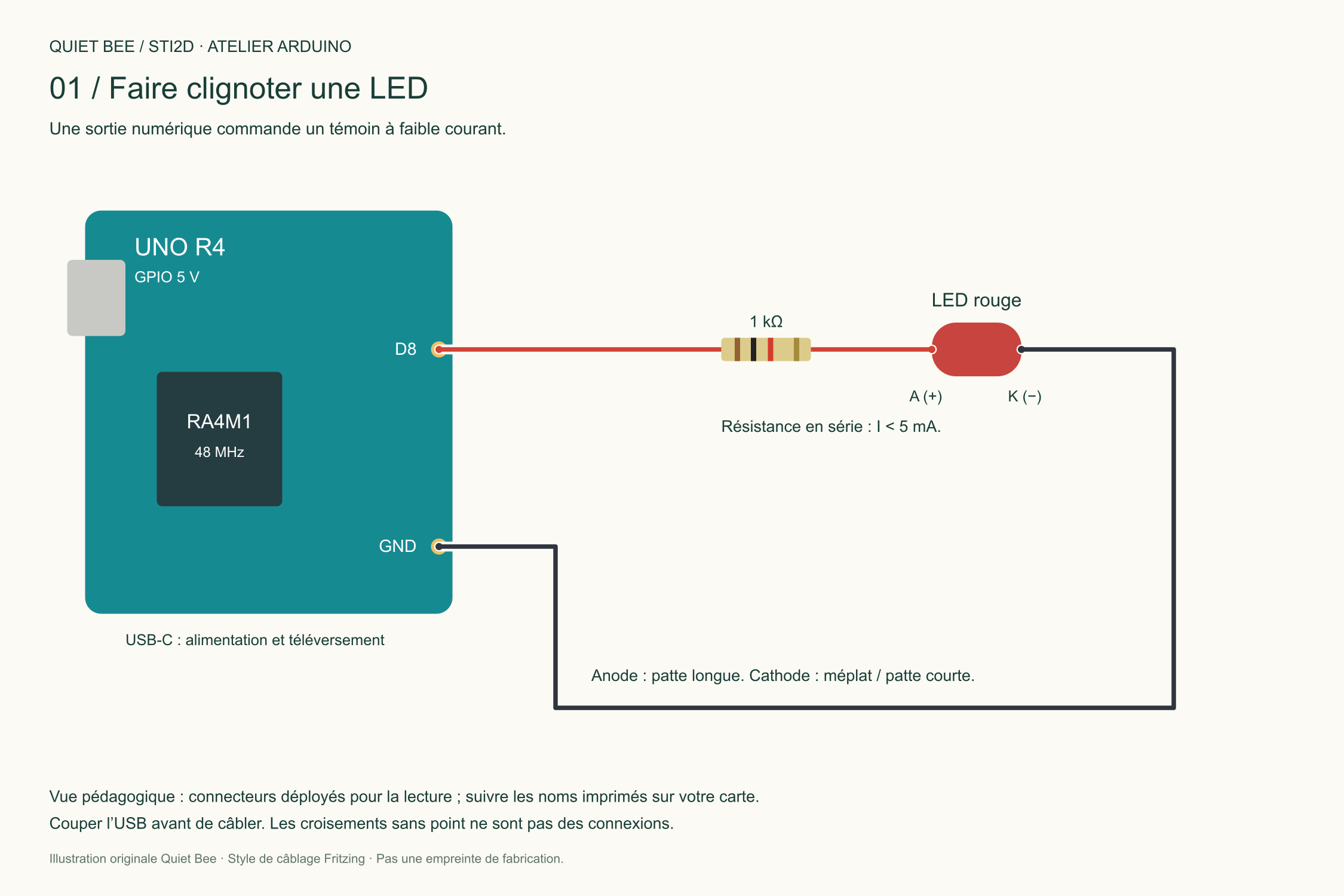
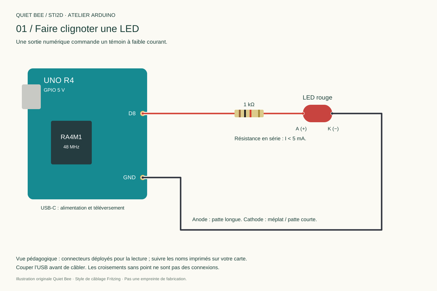
Connect, then check
| From | To |
|---|---|
| D8 | 1 kΩ resistor then LED anode |
| LED cathode | GND |
The resistor is in series. Its orientation does not matter; the LED has polarity. For a red LED with an assumed 2 V drop, the estimated current is (5 − 2) / 1000 = 0.003 A, or 3 mA. Compare this estimate with the LED data sheet and a measurement.
The complete program
01_led.ino
Complete project ↓// UNO R4 Minima ou WiFi. LED externe : D8 -> 1 kohm -> anode ; cathode -> GND.
constexpr uint8_t LED = 8;
constexpr unsigned long PERIODE_MS = 500;
unsigned long dernierChangement = 0;
bool allumee = false;
void setup() {
pinMode(LED, OUTPUT);
digitalWrite(LED, LOW);
}
void loop() {
const unsigned long maintenant = millis();
// La soustraction non signee fonctionne aussi au debordement de millis().
if (maintenant - dernierChangement >= PERIODE_MS) {
dernierChangement = maintenant;
allumee = !allumee;
digitalWrite(LED, allumee ? HIGH : LOW);
}
}
Understand the instructions
| Instruction | Explanation |
|---|---|
pinMode(LED, OUTPUT) | Configures D8 as an output. |
maintenant - dernierChangement | Elapsed time; unsigned subtraction handles counter overflow. |
allumee = !allumee | Inverts a logic state. |
digitalWrite(...) | Sets HIGH or LOW; the resistor limits the current. |
A change every 500 ms produces a 1 s on + off cycle, or a frequency of 1 Hz. Not using delay() keeps the loop available.
YOUR TURN / YEAR 12
Modify the period to obtain a 2 s cycle. What happens to the frequency?
GOING FURTHER / YEAR 13
Propose a cycle with 100 ms on and 900 ms off. How can you store the state and its duration?
Suggested answers
For a symmetric 2 s cycle: 1000 ms between changes, or 0.5 Hz. For a 10% duty cycle, choose the duration according to the current state; a fixed time between toggles is no longer enough.
Validate and troubleshoot
- Observe ten cycles and compare their duration with the prediction.
- LED off: check orientation, GND and D8.
- LED always on: check the circuit and uploaded program.
- Never remove the resistor to “test”.
Next step: Read a logic state →
SOURCES AND FURTHER READING
Check the documentation.
- Arduino UNO R4 Minima · UNO R4 WiFi
- Arduino: analogue converter resolution
- Arduino: WiFiS3 examples
- Analog Devices : DS18B20
- OneWire · DallasTemperature
- Éduscol: STI2D curricula and resources
Original Quiet Bee content. A suggested progression for working on the information chain, prototyping and validation; it does not replace the curriculum or your teacher's instructions.